GeoMenagerie
In this assignment, I learned to implement Bezier Surfaces using de Casteljau algorithm, create smoother surfaces by calculating the normal vectors of the vertices of an object based on an area-weighted average of its surrounding faces, flip and split edges to apply them to the loop subdivision algorithm which increases the number of triangles to create smoother objects, and apply phong and environment shading to add a sense of a texture on the objects. By applying all this, we can produce beautiful 3D objects that are smooth, nicely shaded and textured, and have a sense of realism to them.
Part 1: Fun with Bezier Surfaces
In Part 1, I implemented Bezier surfaces using de Casteljau algorithm. Our goal for this part was to create a Bezier surface from 16 control points that contains points to create an 8x8 grid in parameter space where each box in the grid is made up of 2 triangles. This means I am going to have 128 triangles per grid. To accomplish this, I created an array which would contain the 81 final 3D points which would make up the the Bezier surface. Since the surface is an 8x8 grid, I needed a 9x9 graph to create 64 squares of the grid, hence the array with a size of 81. The uv coordinate plane I was working in went from 0 to 1. Since we needed 64 squares to fit in this plane, I incremented u and v by .125 each step to get the 3D point on the surface corresponding to the given uv coordinates. While deciding how I was going to find the 3D points that create the Bezier surfaces, the preprocess function and matrices or just using de Casteljau algorithm, it seemed much easier to go with de Casteljau algorithm because I could just use it recursively, didn't need to create a 4x4 matrix, and didn't have to worry about the Bernstein polynomial. However, it actually took me a REALLY long time to figure out how I was supposed to implement the algorithm recursively, but I realized since I was always given 16 control points, I can apply the algorithm to shrink to 9 new control points, repeat the algorithm, then have 4 points, then get the final point that I would output in my evaluate function. With the uv coordinates that incremented u and v by .125 respectively and de Casteljau algorithm, we go through each uv coordinate, perform bilinear interpolation based on the control points to see such that if we are currently on the ith and jth control point, it's next point for the next iteration for the algorithm is
next_pi,j = ((1 - u) × (1 - v) × pi,j) + ((1 - u) × v × pi+1,j) + (u × (1 - v) × pi,j+1) + (u × v × pi+1,j+1)Then we do it until we go from the 16 control points to the single point for each uv coordinate. Getting all 81 points would form the 8x8 Bezier surface. Then we make the triangles using the given addTriangle function to turn the surface of quads into a surface of triangles. However, we have to make sure we implement each triangle counter clockwise so that two halfedges of the same edge of a triangle are facing opposite ways. So for a quad made up of (pi,j, pi+1,j, pi,j+1, pi+1,j+1), our two resulting triangles are (pi,j, pi+1,j+1, pi,j+1) and (pi,j, pi+1,j, pi+1,j+1) Figure 1 and Figure 2 show the results of implementing my surfaces.
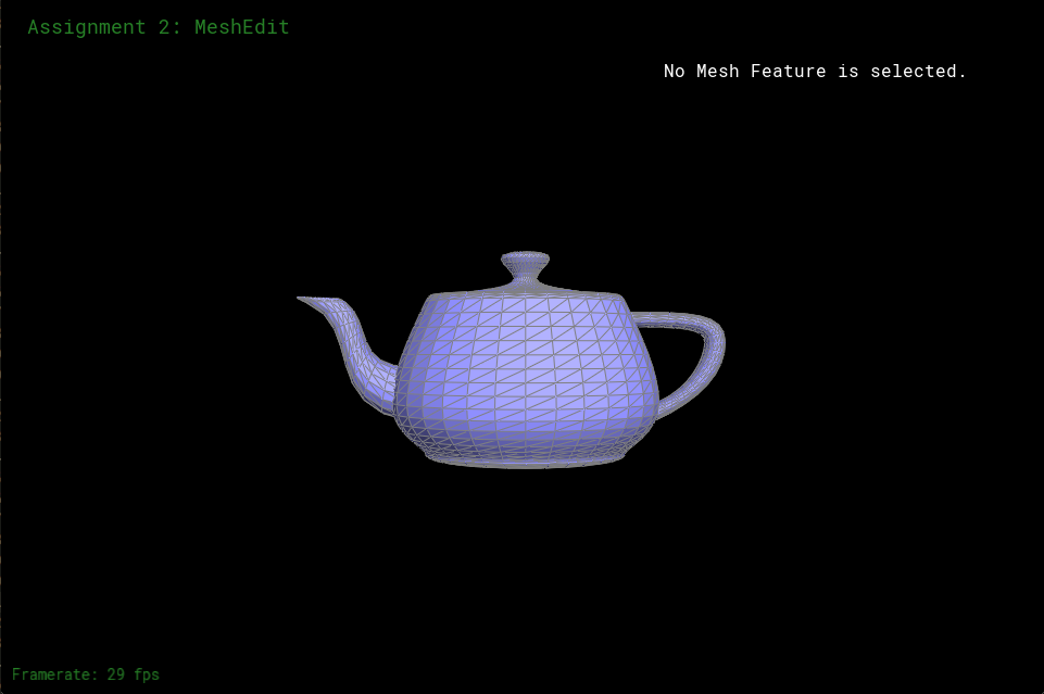
Figure 1: The result showing the edges and faces
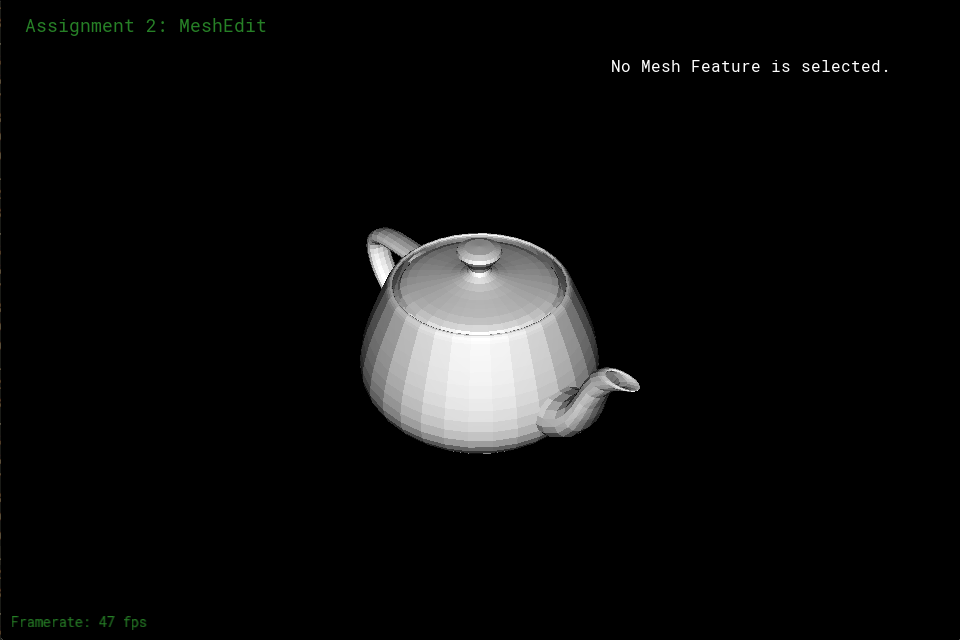
Figure 2: Result without showing where the edges and faces are
Part 2: Average Normals for Half-Edge Meshes
In Part 2, I found a new normal vector for a given vertex. The new normal vector is the sum of the area-weighted normals of the faces touching the given vertex. To accomplish this, I get a vertex's halfedge, get that halfedge's face, then multiply the face's normal by the face's area to get a face's area weighted normal. I then add the area weighted normal to a 3D vector that gets the sum of all the area weighted vectors. I then move to the halfedge's twin's next and get the area weighted normal for it's face and add it to the sum vector. I repeat this until I am back at the original halfedge. If any of the halfedges is a boundary halfedge, I skip it and move on to the next halfedge. Once I get the total sum, I return the sum's unit vector. Figure 3 and Figure 4 show the results of this part.
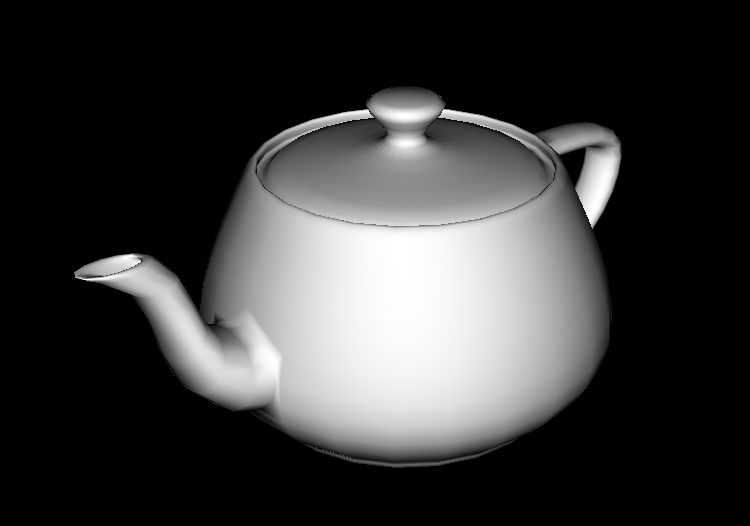
Figure 3: Front of the teapot with averaged normals

Figure 4: Back of the teapot with averaged normals
Part 3: Edge Flip
Edge flipping wasn't too hard. I just made sure that when the edge flips, that each halfedge, especially the halfedges with the flipped edges have the correct neighbors. Then I made each face's halfedge, assigned to the flipping edge's halfedges too make sure a face doesn't stick to a halfedge that it is no longer neighbored to. I also made sure that the vertices that the flipped edge was connected to aren't partnered with the flipped edge's halfedges. Initially, I forgot to account for the faces, so after flipping the same edge twice, I would end up with Figure 6. However, after fixing that, I would end up with Figure 7. Figure 5 shows the original mesh before manipulating edges to turn it into Figure 6 or Figure 7.
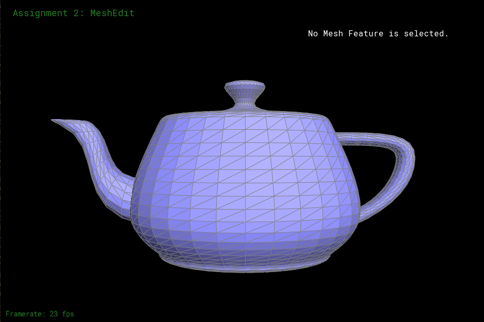
Figure 5: Original teapot mesh
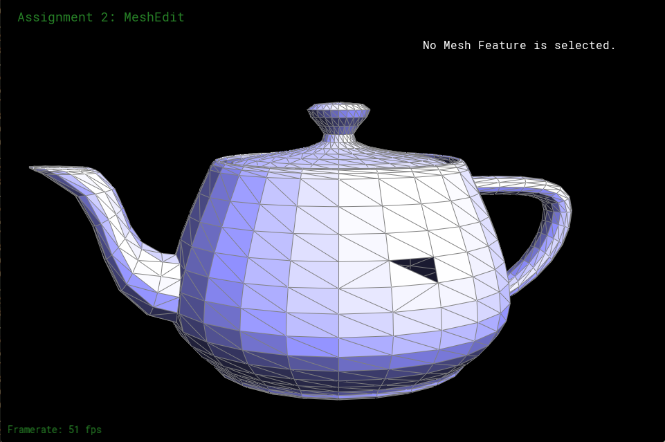
Figure 6: Flip edge mess up due to not accounting for face halfedges
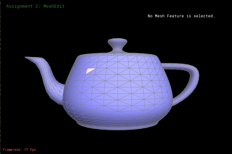
Figure 7: Teapot with flipped edges
Part 4: Edge Split
Unlike part 3, part 4 caused me a lot of problems. They weren't hard to fix because I drew out and labeled all of my faces and edges and vertices as shown in Figure 9. So my intuition was right, but I had a couple mess ups on the code when I was implementing my intuition into the function. One bug was I accidentally switched two vertices. I thought one vertex was another vertex. So splitting an edge would cause my program to crash since it left me with a vertex not pointed to by anything. I also forgot to reset some halfedges' neighbors. For example, for the given edge's halfedge's next halfedge, I forgot to reassign that halfedge's next to one of the newly created halfedges. That would also cause my program to crash as well. This happened with a lot of the outside old edges that weren't changed where I just forgot to set new neighbors for them. So although, I did have more problems than in part 3 and the debugging took a little while, the debugging wasn't hard because I just had to ensure each edge, halfedge, vertex, and face, were neighbored right Figure 8 shows edges that are split and flip while the original is still Figure 5 from part 3.

Figure 8: After flipping and splitting edges
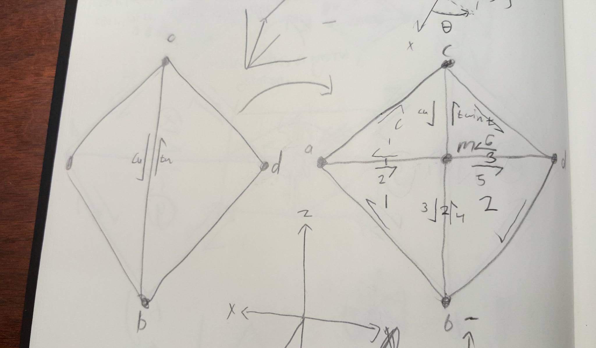
Figure 9: Drawing to help me figure out my problems
Part 5: Upsampling via Loop Subdivision
In part 5, I implemented the Loop subidivison algorithm to create smoother objects after upsampling the number of triangles in a mesh. I stored each vertice's new position based off of its current position and current position of surrounding vertices, stored the new position of future new vertices that are going to be placed at the midpoint of each edge, split every edge of the original mesh, flipped edges that are new and touched an old vertex and a new vertex, then updated every vertice's position to their new position. When applying these steps into my code, I ran into a few problems, Figure 10 shows vertices off point in the icosahedron. It's because I applied edge splitting and storage for new vertice's new position in the same loop causing the result in Figure 10. This also caused the torus in Figure 13 to be wrinkly. To resolve this, I just created a separate loop for storage of new vertices' new position and edge splitting and got the right look for the icosahedron as shown in Figure 11 and Figure 14 and Figure 15 show the right torus. Loop subdivision causes corners to smoothen out due to corner cutting and the old edges begin to curve. I tried performing some splitting before performing loop subidivision in Figure 16 to Figure 30. In Figure 18, after two subdivision of the original cube, the cube isn't symmetric. That's because the edge that cuts through each face of the cube cause this asymmetry. If there were two cuts through each face to make each side symmetric, the symmetry wouldn't disappear after subdividing. So in Figure 19 to Figure 21 I split the edge that cuts through each face to cause symmetry as shown in Figure 19. Results of subdivision show that symmetry is kept and it looks like a smoother square figure. In hope to retain more of the cube shape after subdivision, in Figure 22 to Figure 25, after splitting the edges that cut through the faces, I split all the other faces and the result is Figure 22. In Figure 25, after two subdivisions, the symmetry is still there and it seems like the edges of the original cube don't round out as much. This is because each vertex would use vertices closer than before to gain knowledge of where it's new position would be, so there wouldn't be such a huge shift in position. That means the edges wouldn't round out as much. After trying to split the inside edges and the outside edges of the cube one more time to make each subdivision make the original points move less, I get the results shown in Figure 26 to Figure 30. It looks as though the corners are still a little sharp after the subdivisions, but the edges of the cube now dip in towards the center of the cube at the midpoint of the original outside edges. So to retain the edges of the cube to be as straight a little straighter after a subdivision, I would split as shown in Figure 22. To keep the sharpness of the corners but have the midpoints of two corners dip towards the center, I would split as shown in Figure 26.
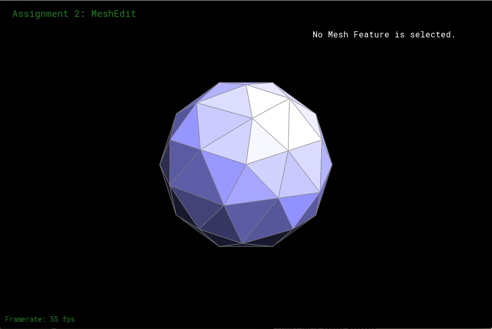
Figure 10: Icosahedron with wrong vertex placement after 1 subdivision

Figure 11: Icosahedron with right vertex placement after 1 subdivision

Figure 12: Original torus
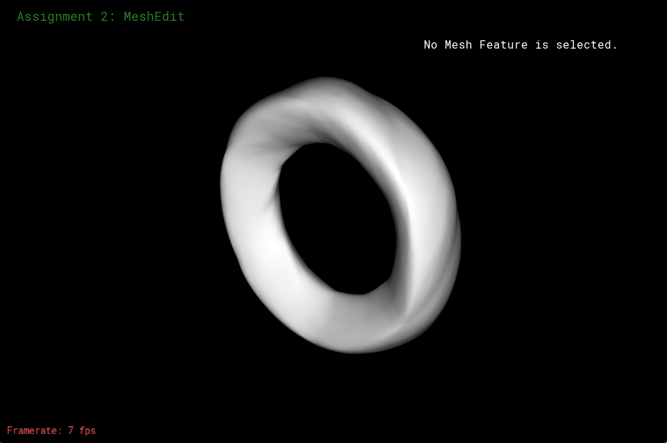
Figure 13: Wrinkly, wrong torus after subdividing

Figure 14: Right torus before average weighted normals
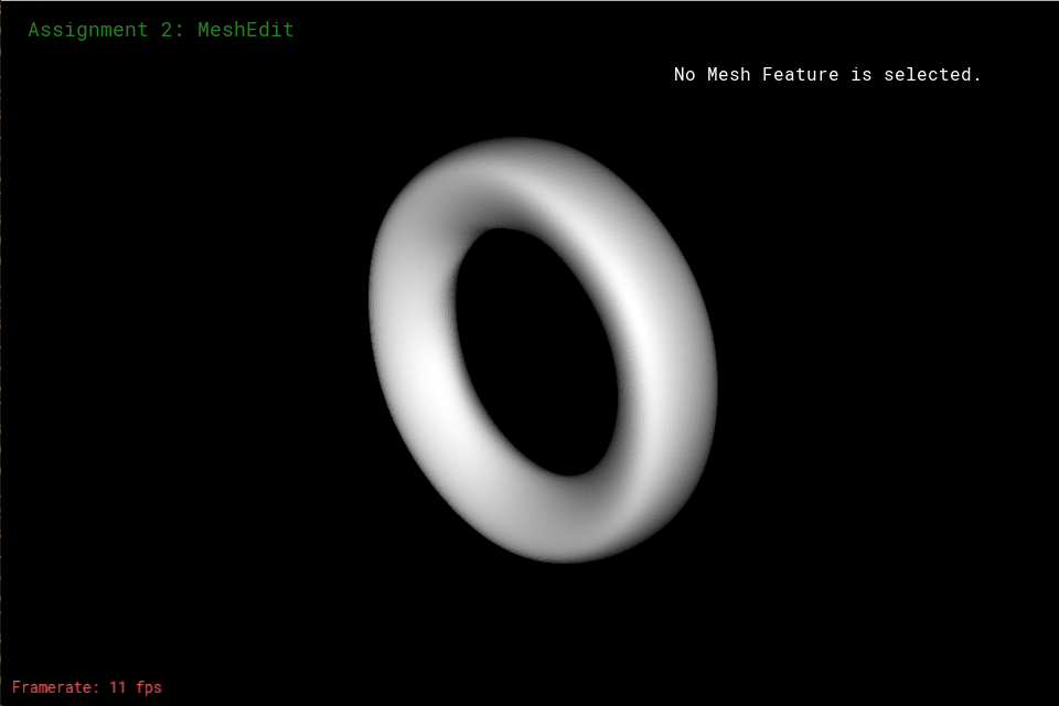
Figure 15: Right torus after average weighted normals
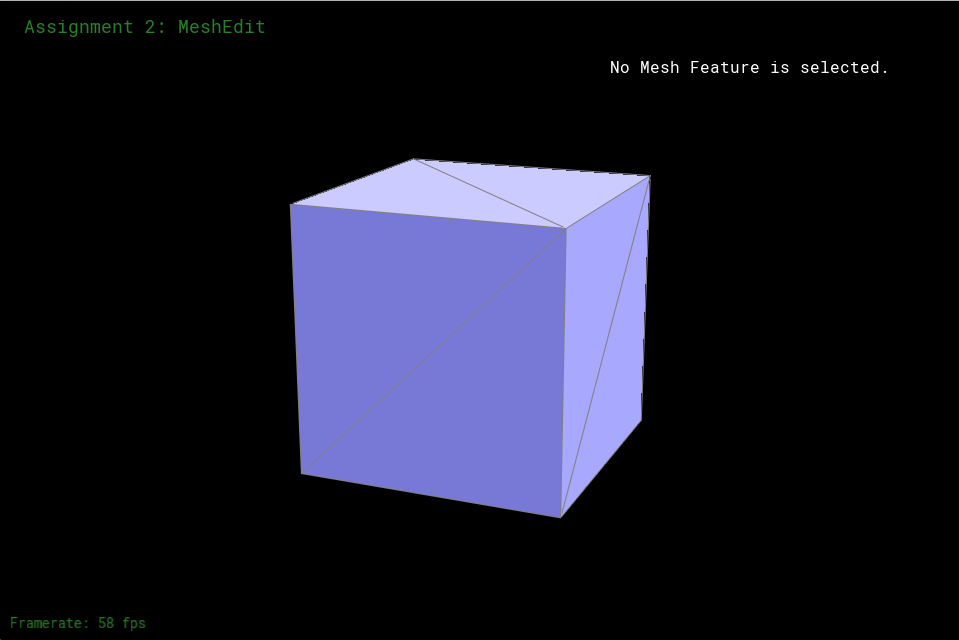
Figure 16: Original square mesh

Figure 17: Original square mesh after subdividing once

Figure 18: Original square mesh after subidividing twice (it is lopsided)
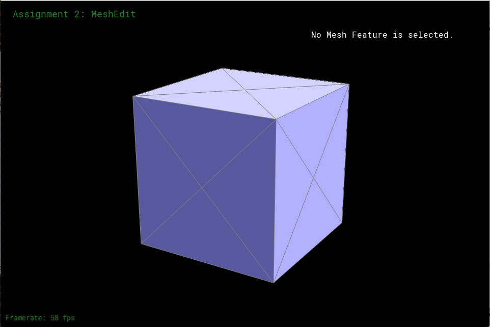
Figure 19: Square mesh after splitting middle edge of each face
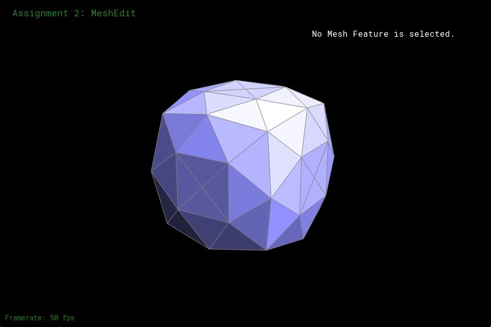
Figure 20: Middle edge split after 1 subdivision
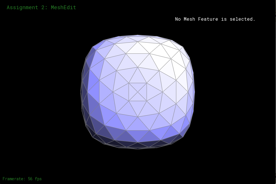
Figure 21: Middle edge split after 2 subdivision
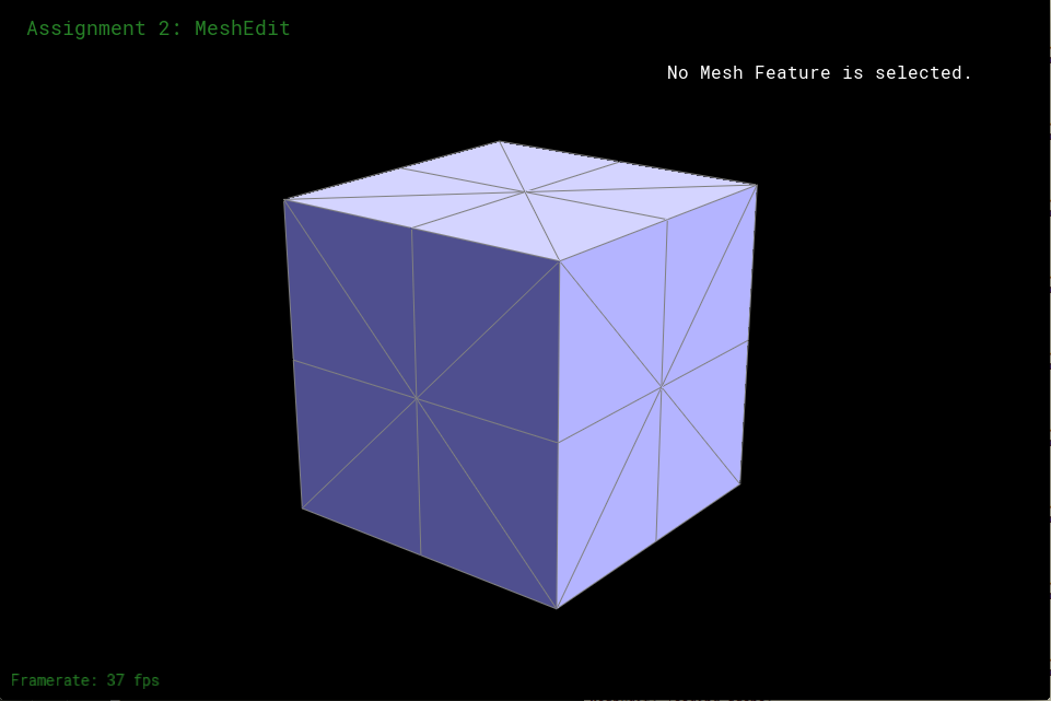
Figure 22: splitting cube edges of Figure 19

Figure 23: 1 subdivision of Figure 22
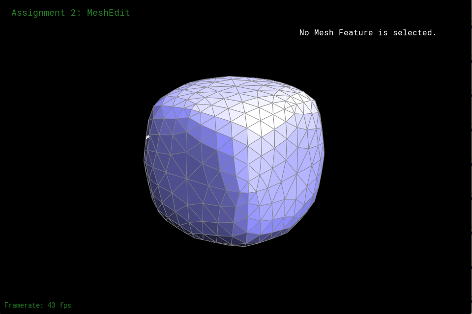
Figure 24: 2 subdivision of Figure 22
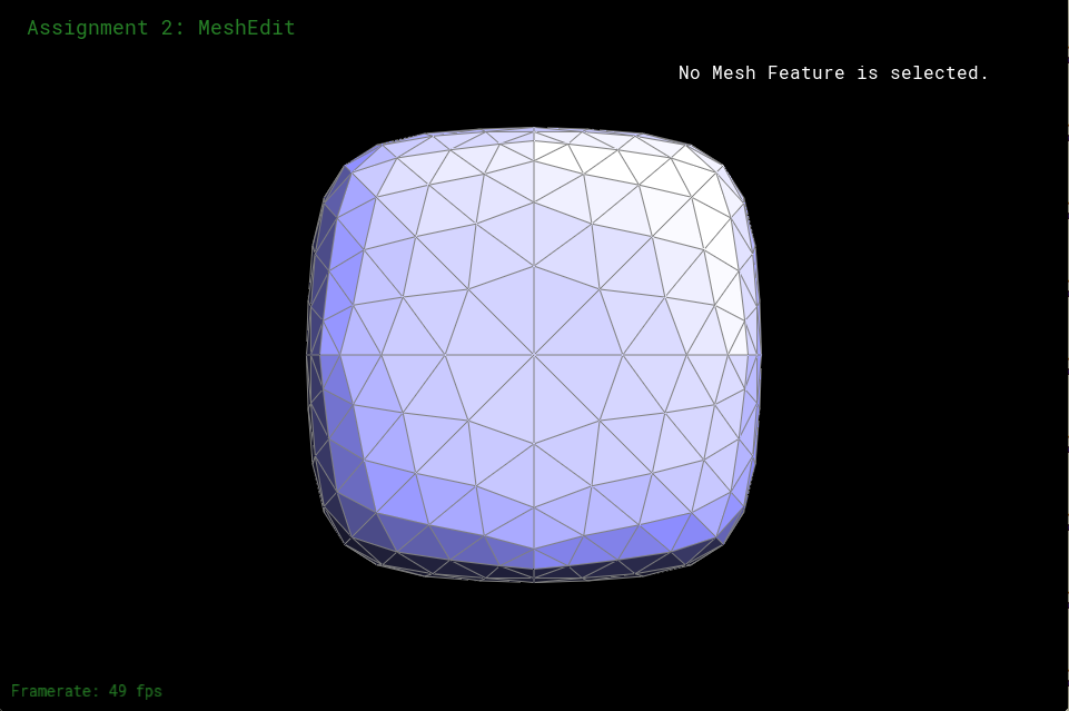
Figure 25: Center of Figure 24 to show symmetry
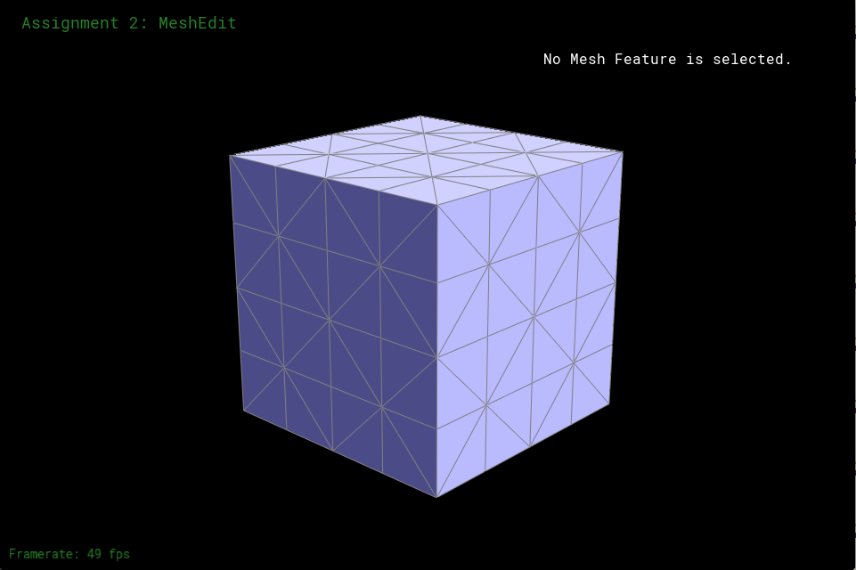
Figure 26: Splitting all middle edges and cube edges again

Figure 27: 1 subdivision of Figure 26
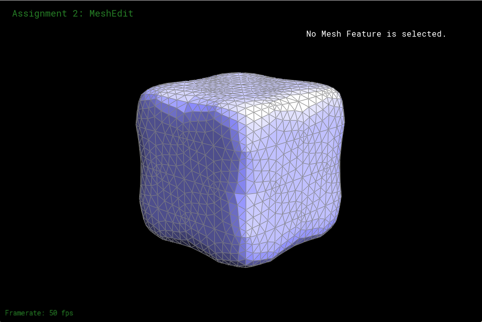
Figure 28: 2 subdivision of Figure 26
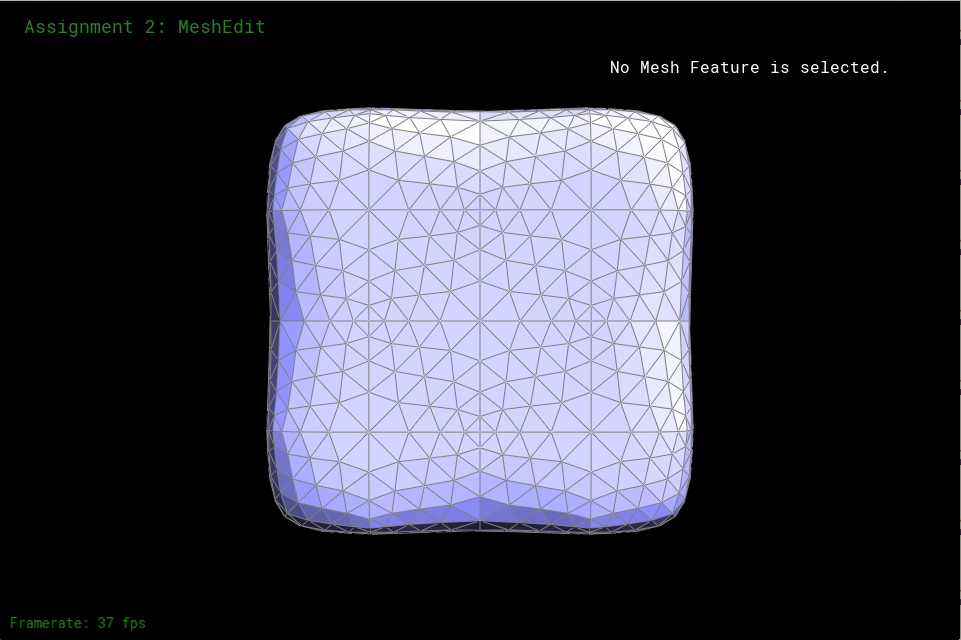
Figure 29: Center of Figure 26 to show symmetry

Figure 30: Figure 29 without showing edges and vertices
Part 6: Fun with Shaders
Part 6 was mainly just applying the formulas we were given in class and in the assignment to create the textures as shown in Figure 31 and Figure 32. To get the phong shading in Figure 31, I had to find the reflected ambient light, La, the diffusely reflected light, Ld, and the specularly reflected light Ls. The reflected ambient light gave it color, the diffusely reflected light gives it a matte finish, the specularly reflected light gives a mirror like reflection of light. We add the 3 of those to get the phong shading, L. To get them we do
La = kaIa
Ld = kd(I/r2)max(0, normal * lightPosition)
Ls = ks(I/r2)max(0, normal * h)p
h = bisector(eyePosition, lightPosition)
L = La + Ld + LsThe k's are constants of our picking, Ia is just the rgb vector of our choosing, and we didn't have to worrying about (I/r2) in this project. The output of the phong shading is shown in Fgiure 31. To get the environment map reflection shading, I followed the instructions and did
refPos = (2.0 * dot(nEyePos,nNormal) * nNormal) - nEyePosI then used the refPos to find the spherical coordinates and used the spherical coordinates to map the texture onto the object resulting in Figure 32.
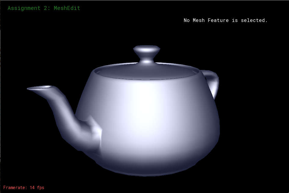
Figure 31: Phong shading
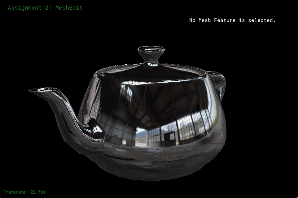
Figure 32: Environment map reflection shading
Part 7: Design your own mesh!
For the competition I made a mesh based on my dog. This one didn't take me nearly as long as the last project because I have experience in Maya so Blender came pretty naturally for me.
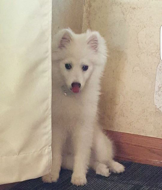
Figure 33: The inspiration for the mesh, my dog. Her name is Rey.
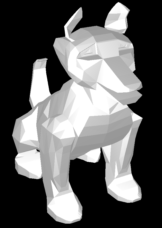
Figure 34: The final submission without any subdivision, I think it looks best this way. It's white cause my dog is white

Figure 35: smoothened before subdivision
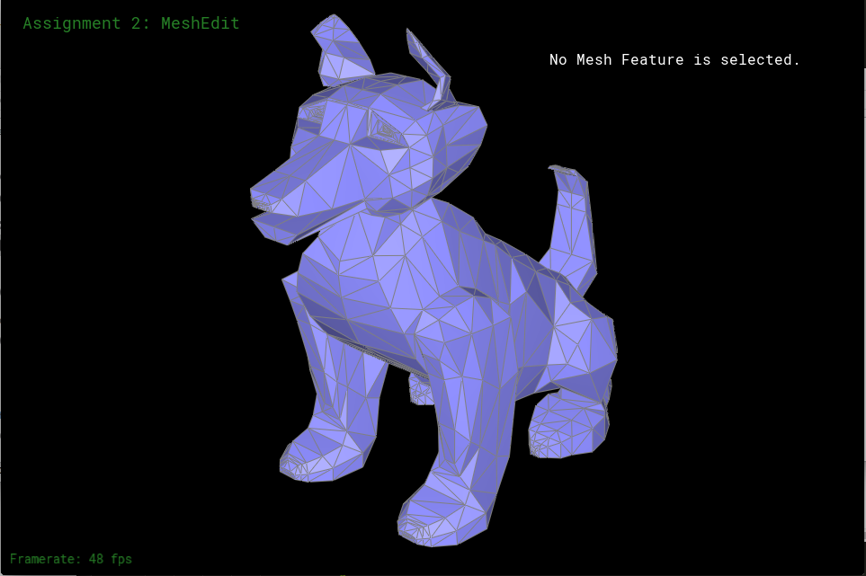
Figure 36: The dog mesh without any edits
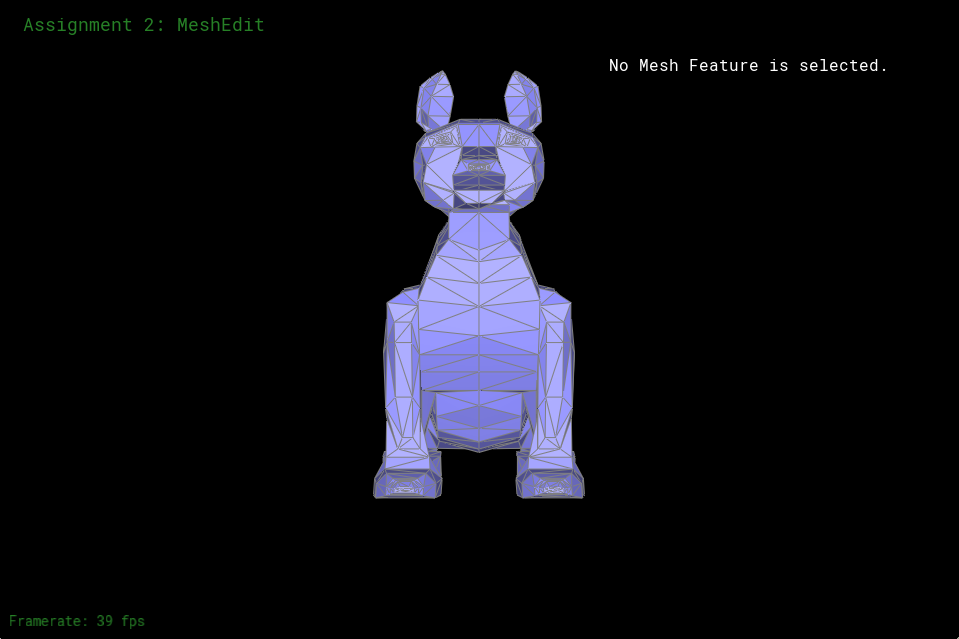
Figure 37: front of dog

Figure 38: side of dog

Figure 39: back of dog
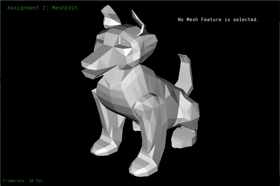
Figure 40: The dog mesh without showing the edges and faces
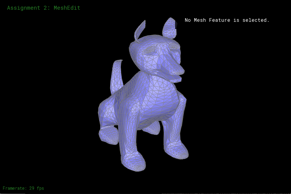
Figure 41: 1 round of subdivision
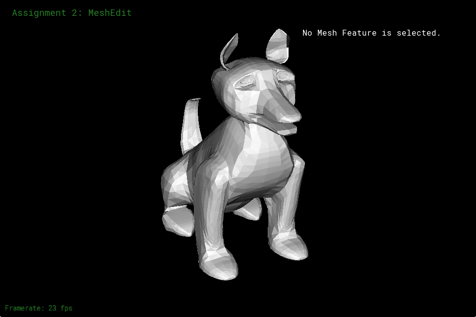
Figure 42: 1 round of subdivision without edges or faces

Figure 43: 2 rounds of subdivision
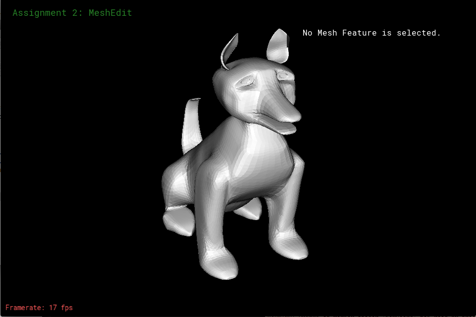
Figure 44: 2 rounds of subdivision without edges or faces
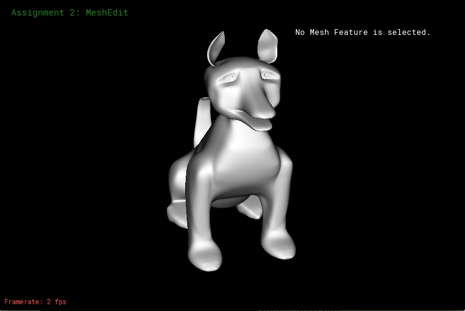
Figure 45: 2 rounds of subdivision smooth
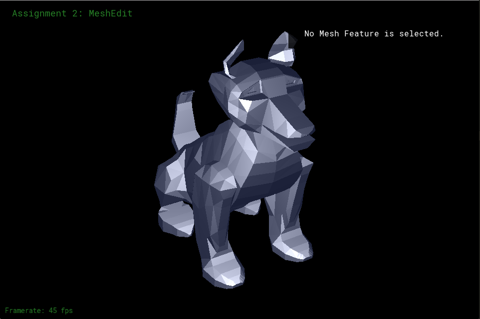
Figure 46: blue phong shading
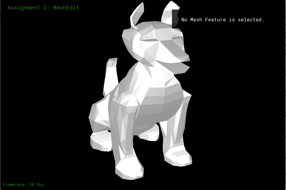
Figure 47: white phong shading

Figure 48: environment shading